Traffic Light
A simple Ladder Logic traffic light system using PLC and HMI.
Manual Traffic Lights
This is a simple program which turn on the lights when the button is pressed
You will need this items to get started:
- Breadboard x1
- PLC x1
- Power supply
- Push-buttons x2
- Stack light or any other thing you want as an output
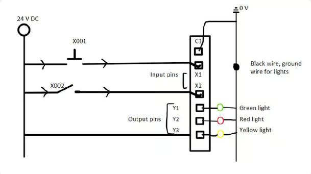
First we have our physical port or address on PLC X001, which is connected to a push-button, when pressed it will start the green light (Y001) which is also connected to the PLC. Something like this…
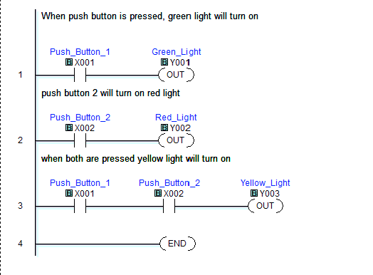
On the first rung we have X1 as Normally Open contact, and an output coil Y1 (green light). Same way we have X2 as N.O. and Y2 for output, which says when the 2nd button is pressed it will turn on the red light. Now, for the third rung we are using both buttons, which says when both buttons are pressed together then it will turn on the yellow light. These contacts (X1,X2) are in series which means it is “AND”.
Feel free to contact me if you need help to understand this. I have brief notes which will explain PLC from the beginning, like its history, how it works, open and close contacts, the architecture of PLC and more.
Applying the same concept while using a HMI (touch screen) instead physical buttons
Items:
- Breadboard x1
- PLC x1
- HMI screen
- Power supply
- Switch
- Ethernet Cable
- Push-buttons x2
- Stack light or any other thing you want as an output
Before we make changes to ladder logic we must ensure that HMI and PLC are on the same network. If they are not then the communication will not happen. Additionally you will have to configure your HMI and add the IP address of the PLC.
HMI Screen
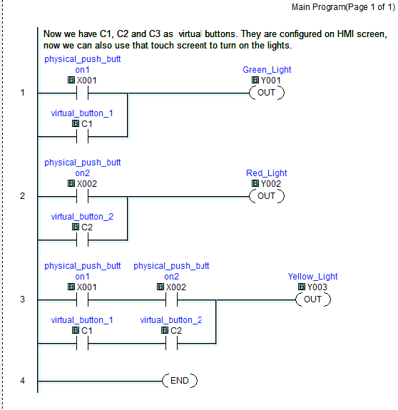
As you can see I have added C1, a virtual bit. This parallel logic is “OR”, which says activate the green light when X1 or C1 is on.
C1 is a virtual bit, you will have to configure it on your HMI. We will do same with the 2nd and 3rd rung.
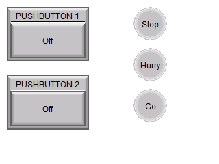
I have also added three indicators which will show the status of the green (Go), Yellow (Hurry) and Red (Stop) lights when the button is pressed.