Conveyor Belt System
A sequenced conveyor-belt control system using PLC ladder logic, timers, indicators, and HMI screens.
Conveyor Belt
Objective: There are three conveyor belts, when a push-button is pressed we want all of them to start automatically one by one in a sequence with a delay, and while this system starts we want an indicator which shows that these belts are starting, and another indicator when the belts are successfully started. Additionally, we will need an HMI for operators to manually start each HMI.
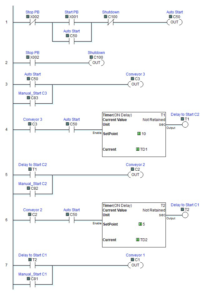
In the first rung, we have our first normally closed contact (Stop PB), it can be considered an interlock. In a normal state, X2 will always be closed, allowing the current to pass through it like a closed circuit.
X1 is a normally open contact (open circuit) that needs to be closed with a push button. In parallel (‘or’) we have the Auto start (C50) as an interlock. Following that, we have a normally closed (N.C.) contact C100, which is used to stop the system from the HMI.
For the output, we have C50 again. The reason we have C50 as an interlock and an output is that it creates a loop. When we close X1 (by pressing the push button), it will activate C50 for a few seconds because a push button closes the circuit only when you push it, but when you release it, the circuit will open, and the system will stop. Therefore, we have an interlock (C50). Once C50 is activated, it will act like X1 is activated, and the process will continue until the C100 is open.
The 2nd rung is for stopping the system.
In the 3rd rung we have C50 as an input, when the C50 will be activated it will turn C3 (conveyor belt 3) on. If you notice we have C83 in parallel to C50, it is for operators to manually start C3 by pressing the button on the HMI.
4th rung has C3 and C50 both as in input to start the delay timer. When C3 and C50 both are on then the timer will be activated which will count to 10 seconds and then it will activate T1.
When T1 is on it will start C2 (conveyor belt 2), if we want just C2 to start without C3, we can use HMI to turn on C82.
Following the same technique C2 will wait 5 seconds and It will activate T2. T2 will start C1 (conveyor belt 1).
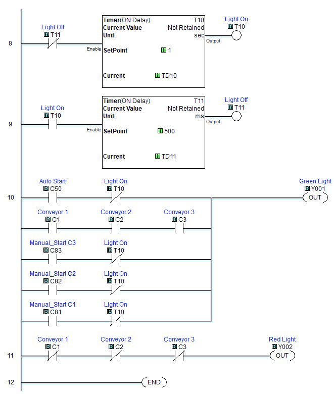
As mentioned in the objective, we require indicators. T11 and T10 will be used to make the light flesh when the belts are starting. T11 is normally closed, therefore the timer will start immediately and will wait for 1 second and then turn on T10.
When T10 is on it will wait 0.5 seconds and then activate T11.
Now if you look at rung 10, you will notice that T10 is already closed. Which that means in the 8th rung, when the T10 will be activated after the delay of 1 second, it will turn off the light. So, the light will be on for 1 second, and it will go off for 0.5 seconds.
In parallel to C50 and T10 we have C1, C2, C3 (conveyor belts). Once all the belts are activated, the blinker (T10) will no longer be used, a solid green light will indicate that the system has started successfully.
We have the same configuration for HMI buttons as well.
In the 11th rung, we have C1-3 as normally close, which says when all the belts are off, a red light will turn on.
Conveyor belt HMI Screen
Home Screen
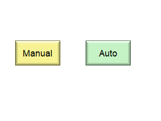
There are three screens, starting from the home screen, we have two options to activate conveyor belts, Manual and Auto. Both option has their individual screens.
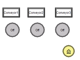
In manual mode we have three buttons in off state, they are for activating the conveyor belt, and the box above them is to show the status of the belt, if belts are on those boxes will have green colour. There is also a home screen button if you want to go back.
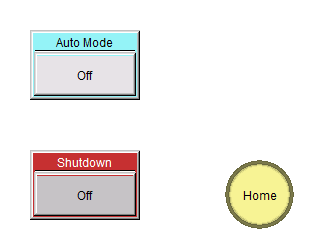
In Auto mode we have two buttons, one to to activate all the belts one by one, this button is C50 on the ladder logic. We also have the shutdown button (C100) to turn off the system.
Manual mode screen
Auto mode screen